Thus if the liquid load is uL 1 m3m2h and the head is ho 1 mm the number of liquid outlets Z required per square metre of column cross-section would be Z 150 in a plate distributor with perforations of d 3 mm diameter. Rei 127Qρ.
2
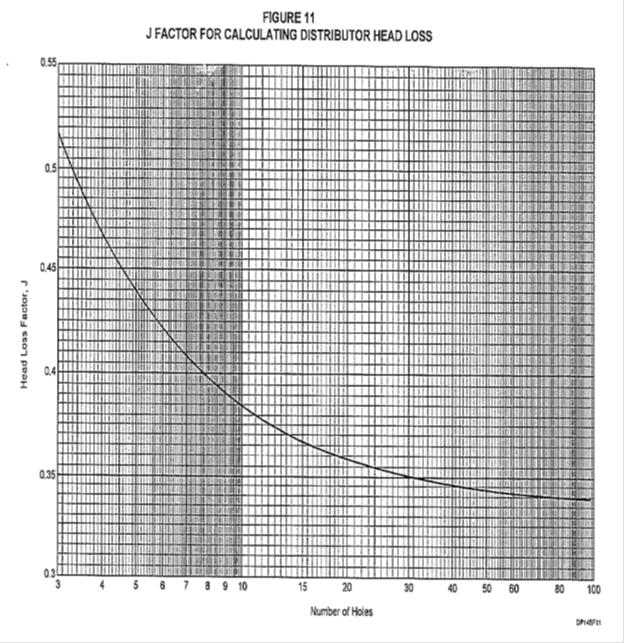
And h PD is the distributor head loss on the vapor side in.

. My experience is that such tests are essential. Since N Re for this case lies between 2 and 500 Terminal settling velocity V t. In this section there are tables that assist in making these factored calculations from the various reference sources.
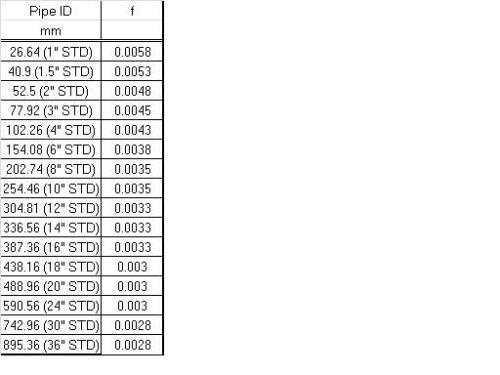
Beams or on packing with special support grid n Redistribution. Calculate the Reynolds number Rei of the inlet stream to the pipe distributor using the following equation. H O is the orifice head in.
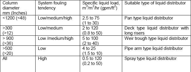
01-25 gpmft 025-60 m3hm2 n Tower diameter. Together with the head h o it allows the flow velocity at an outlet u o and thus the number of outlets required to be determined in distributors with liquid discharge or overflow. 3 ft 900 mm n Support features.
Moore and Rukovena introduced a method to determine the distributor quality based on the drip point pattern 3. A distributor with a free overflow q 40 only saturates the line between the trough with water. This type of liquid distributor has long been the primary device selected for standard performance random packing where liquid flow rates are moderate to high levels.
𝐿 𝑎 𝜇 𝑉 𝑎 Corresponding Reynolds Number N Re for the system can be obtained from GPSA Data book1 Fig. The cross section of the column is divided into circles around each drip point. Determine Process Operation Variables Assumed feed rate composition purity of distillate and bottoms and the quality of the feed are known.
DESIGN CALCULATIONS 71 Selection of Packing Size 72 Rough Design 73 Detailed Design and Rating 8 LIQUID DISTRIBUTION AND REDISTRIBUTION 81 Basic Concepts 82 Pour Point Density 83 Peripheral Irrigation - the Wall Zone 84 Distributor Levelness 85 Maximum Bed Height and Liquid Redistribution. Liquid distribution in the packing is estimated in dependence of the liquid distributor design. Let us straight away get to the steps for sizing a Perforated Pipe Liquid distributor.
The scope of the guide is summarized in its clause headings. What should be verified is the evenness homogeneity of the liquid distribution m3hr of liquid per m2 of section at different areas and at least at nominal and minimum flow rate. The method is sketched in Fig.
In a gravity head distributor this is the sum of the two components. H OA h O h PD 1 where h OA is the total liquid head in the liquid distributor in. Detailed information about the TUMWelChem Cell Model is presented in Hanusch et al.
An overall maldistribution quality is determined as a characteristic value for evaluation. Perform overall material and component balances to determine the compositions of the distillate and bottoms. Separate liquid collector n Standard features 21 turndown ratio.
System 3kgm mPas mNm Phase state 1 Water 987 1463 175 Continuous n-Butanol 846 332 Dispersed 2 Water 999 1323 38 Continuous Cyclohexanone 953 231 Dispersed t t fx tE 2 For r centrifugal separators design and performance calculation is still. Initially set the pipe size of the pipe distributor same as the pipe size feeding the pipe distributor Step 2. The usual equation for flow through orifices is.
In the same column operating at the same load but under a head of ho 3 mm the number required would be Z 80. A typical liquid head level in a v-notch distributor is 13in 2575mm over the entire operating range while a more standard orifice distributor will maintain a head of 312in 75300mm. Trough wall orifices with guide tubes n 2Liquid rates.
The driving force promot-ing coalescence is gravity and in a given system is proportional to r g r being the density difference between the two liq-uid phases. The design of tray hydraulics may be influenced by many factors including process requirements economics and safety. A distributor with a side hole q80 and pipe guidance system creates the best distribution pattern where empty spaces are at a minimum.
900 mm ID with minimum liquid rates in excess of 2 gpmft25 m3hm2. Design of the Liquid outlet nozzle and the Vortex Breaker. Place determine the selection and design of equipment.
1 Physical properties of saturated liquidliquid systems Henschke 1995. 4 Design Philosophy 5 Performance Guarantees 6 Description of Packed Column Internals 7 Design Calculations 8 Liquid Distribution and Redistribution 9 Practical Aspects of Packed Column Design In addition Appendices give examples of design calculations by various methods for both. Diameters greater than 36 in.
Siretb Chemical 17 May 10 0236. Liquid distributor test for columns. L G x ρg ρl05 0042002778 x 11846110005 000497 Use the 000497 as ordinate and pressure drop of 1471 NSqmm find the abscissa from the below graph.
According to Bernoullis equation total head at a ny given point in liquid unde r motion is the sum of pressure velocity and elevation heads. These styles of liquid distributors consist of a perforated deck with holes or drip tubes for the liquid and round or rectangular risers for the vapor. Generally path flow liquid on tray is divided into single pass two pass three pass and four pass.
Liquid distribution in the packing is calculated in a top down sequence following a three-step distribution mechanism which considers the geometrical shape of the packing as well as the operating parameters liquid and gas load. Liquid leaving the packing L inlet liquid flow rate Component removed 00207 00214 00420 KgSec. 7 Model 186 Trough Distributor Model 196 Packed Trough Very Low Flow Distributor n Metering device.
A distributor with a base hole q60 generates a concentrated area below the trough. 900 mm Orifices in base Liquid rates between 2 and 16 gpmft25 40 m3hm2 The Model 126 Intalox distributor and Model 127 redistributor are designed for towers greater than 36 in. In determining the settling velocity in a liquid-liquid disper-.
Graphical Determination of a Distillation Column Design Step 1. The diameter of the droplets is a critical parameter. Z g V h P 2 2 2 Where h total head feet P pressure head feet V velocity ftsec g gravitational acceleration 322 fts2.
A crucial parameter in the design of a distributor is the liquid load uL required for the separation process. Liquid distributor test for columns. Since liquid head above the orifice is a major component of flow uniformity the lower head distributors typically have a lower-quality distribution than higher head designs.
Column Internals Explained Part 2 Separation Technologies

Importance Of Liquid Distributors Part 1 Mach Engineering
Perforated Pipe Distributor Sizing Calculations Cheresources Com Community
Perforated Pipe Distributor Sizing Calculations Cheresources Com Community

Column Internals Explained Part 2 Separation Technologies

Column Internals Explained Part 2 Separation Technologies
2

Distributors Pressure Drop Brewiki
0 comments
Post a Comment